 |
OpenSNES
Modern Open-Source SNES Development SDK
|
|
OpenSNES
Modern Open-Source SNES Development SDK
|
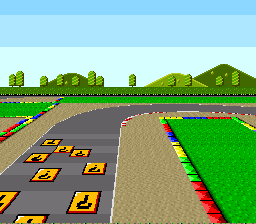
examples/mode7/perspective: the Mode 7 plane receding to a horizon, one HDMA-fed matrix per scanline.
This tutorial covers SNES Mode 7: what the affine background mode actually is, why its VRAM format is interleaved, the matrix maths the lib hides behind mode7SetAngle/mode7SetScale, and how the F-Zero / Pilotwings "perspective ground plane" pattern is built by combining Mode 7 with HDMA. It assumes you have read the Graphics tutorial and (for the perspective section) the HDMA tutorial.
The SNES PPU has eight BG modes, numbered 0–7. The first seven (Mode 0 through Mode 6) are variations on tilemap-based rendering with different colour-depth / layer-count tradeoffs. Mode 7 is the odd one out:
This is the mode F-Zero, Super Mario Kart, Pilotwings, and Final Fantasy VI's airship use. The single-layer / 128 × 128 / 8 bpp restrictions are the cost of the affine transform — which the SNES PPU does in hardware once per frame, not per scanline.
(Per-scanline matrix changes — the F-Zero "ground recedes into the distance" effect — are not a Mode 7 feature; they are HDMA writing new matrix values every scanline. See the perspective section below.)
The Mode 7 affine transformation maps each screen pixel (x, y) to a tilemap coordinate (X, Y) through a 2 × 2 matrix and two centre / scroll offsets:
The registers live at $211B–$2120:
| Register | Name | Purpose |
|---|---|---|
| $211B (write twice) | M7A | Matrix top-left, signed 1.7.8 fixed-point |
| $211C (write twice) | M7B | Matrix top-right |
| $211D (write twice) | M7C | Matrix bottom-left |
| $211E (write twice) | M7D | Matrix bottom-right |
| $211F (write twice) | M7X | Centre X (signed 13-bit) — cx in the formula above |
| $2120 (write twice) | M7Y | Centre Y (signed 13-bit) — cy |
| $210D (BG1HOFS, write twice) | scroll X | sx |
| $210E (BG1VOFS, write twice) | scroll Y | sy |
| $211A | M7SEL | Flip + out-of-bounds behaviour |
All of $211B–$2120 are double-write registers: write the low byte first, then the high byte, to the same address. The 65816's STA to a 16-bit register doesn't do this for you — the lib's helpers sequence the writes correctly.
Mode 7's biggest gotcha lives in the VRAM layout. To save bandwidth, the PPU stores the tilemap in the low byte of each VRAM word, and the tile pixel data in the high byte of each VRAM word — both occupying the same address range $0000–$3FFF.
This means a single VRAM word at address N contains:
Implications:
The lib hides this: dmaCopyVramMode7(tilemap, tilemapSize, tiles, tilesSize) runs the two DMAs (tilemap into the low bytes with VMAIN=$00, tiles into the high bytes with VMAIN=$80), reads each pointer's bank, and every Mode 7 example calls it once during forced blank. The asset-loading step is one call.
The minimum sequence to bring up a rotating Mode 7 plane:
Three things to remember:
The default after mode7Init():
mode7Init() also sets the scale the angle helpers use to 0x0100, 1:1, so a first mode7SetAngle(0) keeps the identity.
The centre is a point of the plane, and it shows on screen at (centre − scroll): the PPU computes plane = M × (screen + scroll − centre)
, so the screen pixel where screen + scroll = centre is the one that does not move. To rotate around the screen centre, keep the two 128 × 112 apart: mode7SetCenter(sx + 128, sy + 112) for a scroll of (sx, sy).
The scale is in texels per screen pixel, 8.8 fixed point: mode7SetScale(0x0100, 0x0100) gives A = D = $00FE, 1:1 (the sine table peaks at 127/128). 0x0080 magnifies twice, 0x0200 shrinks twice (you see four times the area). Smaller is closer, counter-intuitive at first, but the formula tells you why: a larger A/D means each screen pixel steps over more plane pixels. (Before 0.48.0 the helpers wrote half the scale, so 0x0200 was 1:1; code written then halves its scales.)
What happens at screen pixels that map outside the 128 × 128 tilemap? Three options, controlled by the high two bits of M7SEL ($211A), exposed via mode7SetSettings():
| Constant | Behaviour |
|---|---|
| MODE7_WRAP (0x00) | Tilemap wraps. The 128 × 128 tile pattern repeats infinitely. Default. |
| MODE7_TRANSPARENT (0x80) | Out-of-bounds is transparent — show backdrop colour or a layer below (in modes that combine layers, but Mode 7 has only BG1, so this means backdrop). |
| MODE7_TILE0 (0xC0) | Out-of-bounds always shows tile 0. Useful when the tileset's tile 0 is a "border" or "void" graphic. |
For a flying-game where the player can fly far in any direction, WRAP gives an endless ground. For a fixed-arena game (a Mode 7 chess board, say), TRANSPARENT or TILE0 keeps the world bounded.
| Function | Purpose |
|---|---|
| mode7Init() | Identity matrix, centre (128, 128), M7HOFS 0 / M7VOFS $17F; helper scale 0x0100 (1:1). Does not set BG_MODE7. |
| mode7SetScale(sx, sy) | Set the helpers' X/Y scale, 8.8 texels per pixel (0x0100 = 1:1, 0x0080 = magnified twice), up to 0x3FFF. Stored; applied on next mode7SetAngle. |
| mode7SetAngle(angle) | 0–255 angle (full circle wraps at 256). Looks up sin/cos from a table, multiplies by current scale via the hardware multiplier, writes M7A–M7D. |
| mode7SetCenter(x, y) | Set the rotation centre (cx, cy) in tilemap coordinates (signed 13-bit). |
| mode7SetScroll(x, y) | Set the scroll offsets (sx, sy) in tilemap coordinates (signed 13-bit). |
| mode7Rotate(degrees) | Convenience: take 0–359 degrees and convert to the 0–255 internal angle. |
| mode7Transform(degrees, scalePercent) | Combined rotate + scale: 100 = 1:1, 50 magnified twice, 200 shrunk twice (percent × 2.5, so 100 is 0x00FA). |
| mode7SetExtBg(on) | EXTBG (SETINI bit 6): BG2 shows the same plane, bit 7 of each pixel as its priority — a second layer around the sprites. See below. |
| mode7SetMatrix(a, b, c, d) | Direct matrix control. Bypasses the angle/scale system. For shears, non-uniform scales, or arbitrary affine effects. |
| mode7SetSettings(M7SEL_value) | Flip + out-of-bounds behaviour (the constants above). |
The "hello-world" of Mode 7. mode7SetAngle() and mode7SetScale() update the matrix every frame in response to D-pad input — A/B rotate, UP/DOWN zoom. Read the example to see the exact init sequence (consoleInit, setScreenOff, asm_loadMode7Data, setMode(BG_MODE7, 0), mode7Init, mode7SetScale, mode7SetAngle, setMainScreen(TM_BG1), setScreenOn) and the per-frame update path. ~100 lines of C; the entire demo fits on one screen.
The trick that gives Mode 7 its reputation. The 2 × 2 matrix is constant per frame in plain Mode 7, which means the BG plane stays "flat" — no perspective. To create the F-Zero "ground recedes into the distance" effect, you write different matrix values per scanline using HDMA on the M7A and M7D registers.
The example is a 4-channel HDMA orchestration:
Read the example's asm_setupHdmaPerspective for the table-build algorithm. The math is straightforward: for scanline s at distance d from the horizon, the matrix factor is 1.0 / d (inverse depth). What's hard is the channel bookkeeping — get the timing wrong and you see the wrong mode for one scanline, or the perspective curve "jumps".
This is also a textbook case for the HDMA tutorial's gotchas: the example uses HDMA channels 1–4, leaves channel 0 for dmaCopyVram and channel 7 for the OAM DMA. Run any other split-mode display through it; the scaffolding is the same.
Same four-channel split as perspective, but the M7A–M7D tables are not precomputed: the DSP-1's Raster command streams them every frame for a real camera (position, height, heading, tilt), so the floor rotates and moves in true perspective. The M7A/M7B pair rides one HDMA_MODE_2REG_2X channel and M7C/M7D the other, double-buffered and swapped with hdmaSetTable in VBlank. The geometry that pins the matrices to the screen — horizon raster, Mode 7 centre and scroll — comes from dsp1SetCamera; see the DSP-1 tutorial.
Mode 7 draws one layer — unless SETINI bit 6 (EXTBG) is set, mode7SetExtBg(1). Then BG2 shows the same plane as BG1 (same tilemap, same pixels, same transform), but reads bit 7 of each pixel as a priority bit and bits 0-6 as its colour, 128 colours. Front to back, Mode 7 EXTBG draws (anomie's register doc, Mode 7):
| 1 | sprites, priority 3 |
| 2 | sprites, priority 2 |
| 3 | BG2 pixels with bit 7 set |
| 4 | sprites, priority 1 |
| 5 | BG1 |
| 6 | sprites, priority 0 |
| 7 | BG2 pixels with bit 7 clear |
So a priority-1 sprite passes in front of the bit-7-clear pixels and behind the bit-7-set ones — a ball rolling over a floor and under a bridge drawn in the same plane. Put BG2, not BG1, on the main screen (setMainScreen(LAYER_BG2 | LAYER_OBJ)): BG1 sits above BG2's low pixels and would cover them. The two layers are not transformed or scrolled independently, and BG2 does not take direct colour (snesdev-wiki, Backgrounds). Colour your pixels knowing that BG1 reads all eight bits: 0x83 is colour 3 on BG2 and colour 131 on BG1.
examples/mode7/extbg runs a sprite under a row of pillars and toggles EXTBG with A.
$210D/$210E and $211B-$2120 all go through a single shared prev-byte latch. If an HDMA channel or an IRQ writes a BG1 scroll register between the two writes of a Mode 7 register, the value — and the Mode 7 multiplier result MPY ($2134-$2136) — is silently corrupted (documented in the snesdev-wiki Errata). Practical rule: do matrix writes and MPY reads during VBlank, or disable any BG1-scroll-driving HDMA channel while rewriting the matrix. The perspective example is safe as shipped: HDMA channels run sequentially within a scanline, so one channel's two-byte M7A write is never split by another channel — the hazard is CPU-side matrix writes or MPY reads racing a scroll-writing HDMA channel mid-frame. dsp1_ground follows the rule the other way round: its HDMA channels own M7A–M7D all frame long, so every CPU-side Mode 7 write (mode7SetCenter, mode7SetScroll) happens in VBlank, and mode7SetAngle — which also reads MPY — is never called while the split is live.
Mode 7 disables BG2, BG3, BG4 in hardware. setMainScreen(TM_BG1 | TM_BG2) does nothing useful; only BG1 renders (the one exception is EXTBG, SETINI bit 6, which turns BG2 into a priority-split copy of BG1 — not a second tilemap). If you want a sky on top of a Mode 7 ground, you HDMA the BGMODE register mid-frame (see the perspective example). There is no "Mode 7 + a normal tilemap" mode.
OBJ (sprites) work as normal in Mode 7 — they are not BG layers and are not affected by the mode switch. You can put sprites on top of a Mode 7 plane.
dmaCopyVram() writes to both bytes of each VRAM word; for Mode 7 you want only the low byte (tilemap) or only the high byte (tile data) per pass. dmaCopyVramMode7() is that two-pass loader, and it is what the examples call. What it does, if you ever need a partial load by hand:
Reach for this only for a partial tile set or a map region; the whole-set case is the one call above.
M7A–M7D, M7X, M7Y, BG1HOFS, BG1VOFS are all double-write registers — the SNES PPU expects the low byte then the high byte, and remembers the previous "low byte" between writes. If you write to another double-write register in between, the next high-byte write goes to the wrong place.
The lib's helpers do this correctly. If you write to M7A–M7D directly (via mode7SetMatrix or by hand), keep all four matrix writes together — don't intersperse with other PPU writes.
mode7SetAngle reads the current scale to compute the matrix. Reverse order writes the matrix using stale scale values for one frame; the next mode7SetAngle call corrects it. Cosmetic, but visible as a one-frame "blip" when you change scale and angle in the same frame.
mode7Init sets the centre to (128, 128); the middle of the 256 × 224 screen is (128, 112) when the scroll is (0, 0). To rotate around the screen centre, call mode7SetCenter(sx + 128, sy + 112) for a scroll of (sx, sy).
This trips people up: "my plane rotates correctly but isn't centred on screen".
Mode 7 has no other BG to "see through to". MODE7_TRANSPARENT shows the backdrop colour (CGRAM[0]) where the tilemap doesn't extend. If you want a sky behind the Mode 7 plane, you must HDMA the BGMODE register to switch to a different mode for the sky region of the screen — see the perspective example.
Mode 7's affine transformation is computed in PPU hardware, not on the CPU, so the display of a Mode 7 plane is free. The CPU cost lives in the matrix updates:
Per-frame matrix updates are cheap (well under 0.1 % of the frame). Per-scanline updates via HDMA are more expensive — see the HDMA tutorial's cycle-cost section. The 4-channel perspective example consumes ~6 % of CPU during active display.
mode7/perspective drives M7A/M7D per line for the F-Zero ground; mode7/perspective_rotate drives the FULL matrix — cos into M7A and M7D, sin/-sin into M7B/M7C — from 48 pre-built angle tables (entry = trig(2*pi*a/48) * 20480 / scanline, 8.8 fixed: the hyperbolic perspective divide). Four HDMA channels, one per register, repointed per frame with hdmaSetup(ch, HDMA_MODE_1REG_2X, HDMA_DEST_M7A..D, table + angle * 673). The tables are machine-verified by opensnes-image perspective, which regenerates them from that formula (res/perspective.toml; its golden suite holds krom's bytes).
 1.16.1